


17-69

User
OL-26572-01


Chapter
Displaying

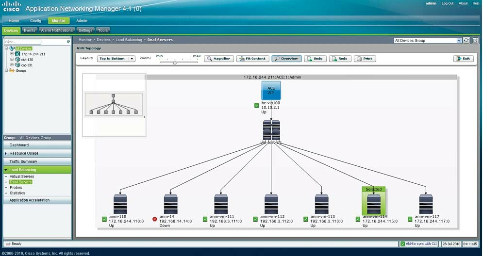
Figure
Sample


3


3a


3b


1


2
Ta
Network
Item
Description
1
Topology
Layout—Changes
drop-down
Zoom—Modifies
map.
bar
the
Magnifier—Toggle
that
When
the
the
Fit
map
Overview—Toggle
Undo—Sets
the
previous
Redo—Redoes
Print—Sends
topology
printer.
Exit—Closes
the


